This section will explain the methods used to transfer the drivers energy to the transmission system and enable the vehicle to be slowed or held stationary.
BRAKE PEDALS
There are a number of options for pedal design, usually dictated by ergonomics, packaging & system type. The force ratio can be determined by the distance from the foot to the pivot divided by the distance from the output pushrod to the pivot. 4.5:1 would be typical.
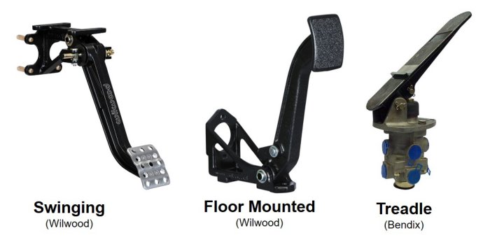 Figure 1: Brake Pedal Design Options
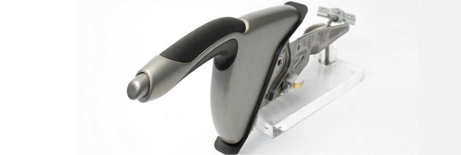
BRAKE LEVERS
Generally levers can be treated in the same way as pedals but the off highway, over-centre lever is a bit different. The ratio is exponential and increases to infinity as the travel tends to zero. To determine an effective ratio the stiffness of the brackets and cable must be determined.
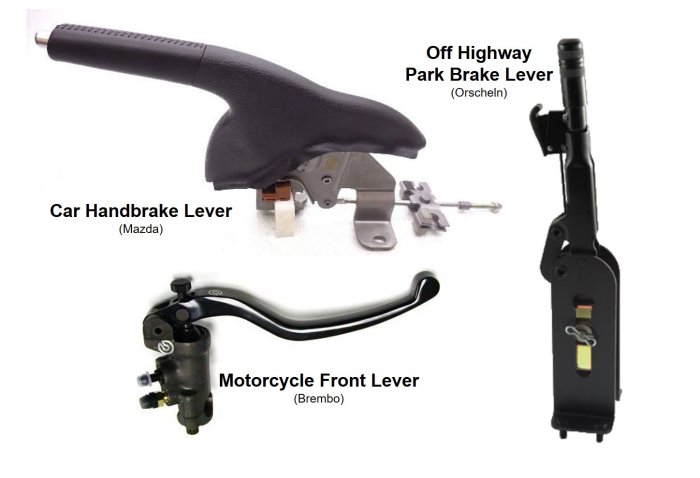 Figure 2: Brake Lever Designs
APPLYING THE BRAKES
Passenger car regulations in Europe require a pedal effort less of than 500N to give a deceleration of 6.43m/$s^2$ but a more typical effort would be 150N at 75mm travel. These could rise to 350N and 90mm for a truck or tractor where the ergonomics are different. The actuation limit is work = force x distance (Joules) If the system requires more work than the driver can input then some form of assistance is required.
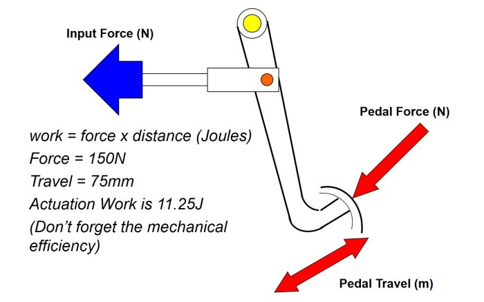 Figure 3: Typical Car Brake Pedal Input Energy
Allowing for a bit of friction lost in the pedal pivots it can be assumed the driver can apply about 10J.
If the brake system requires more energy to operate than this then some external energy source is required.
The system energy can be calculated the same way as the pedal. What is the applied force and how much travel is required. You will have to add up all the brakes controlled by this pedal.
For example, two calipers on the front axle and two drum brakes on the rear axle.
You can find more details on the foundation brakes and braking systems pages.
This method can also be used for hand operated levers; parking brake, motorcycle or cycle handlebars etc.
VALVES
Unless a cable is used, some sort of valve is required to control the transmission medium.
In most passenger cars the transmission medium is brake fluid and the valve is a master cylinder, but for larger vehicles a hydraulic valve or air valve may be used. A small number of vehicles use electronic control where the valve is replaced with a position sensor and spring / damper pack. .
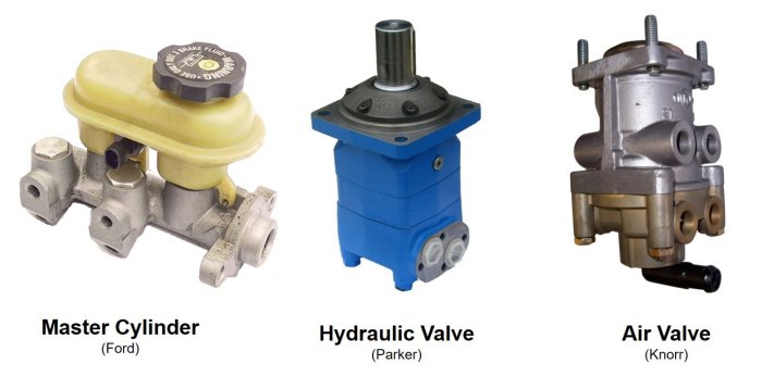 Figure 4: Brake Valves
ENERGY SOURCES
Where the energy available from the driver isn't sufficient for that required by the brake system an external energy source is required.
Depending on the amount of mismatch a number of options are available;
If the drivers energy IS capable of meeting the secondary braking legislation. For ECE R13H that is a pedal effort of less than 500N giving a deceleration of 2.44m/$s^2$, then a boosted system can be used.
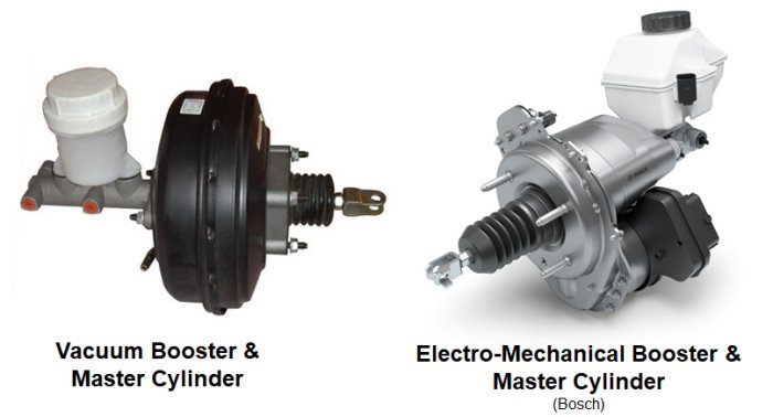 Figure 5: Brake Boosters
If secondary braking cannot be achieved by the drivers muscular energy then a full power braking system will be required. Full power systems for road vehicle are usually Air Brake Systems, fitted to most large trucks but can also be Power Hydraulic Systems typically fitted to Off-Highway machinery. These systems require an engine driven pump or compressor, energy storage and complex valving to ensure safety in the event of failure.
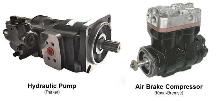 Figure 6: Brake Pumps & Compressors