|
|
||||||||||||
| home > projects | |||||||||||||
mp3 amplifier
This information dates from 2007
I did have a look around to see if a commercial product was available but I couldn't find anything quite right. I did find an american site however which has a good description of how to build an amplifier for a minidisc player. It looked good to me so I worked out the equivelent components available from Maplin and set about copying it.
Now I don't pretent to be any good at electronics and haven't a clue how it works but it does, so here's a link to the guy who did the hard work:- Stephen H. Lafferty.
Well to be truthful it didn't quite work, but by deleting a couple of components it did! The components deleted are to reduce the audible noise by reducing the gain. I sat and listened with my high quality Sennheiser HD490 headphones on and couldn't detect anything untoward so I'm sure it'll be fine near the perfect listening environment of one of Edward Turner's parallel twins!
I don't propose to copy the detail from Stephen H. Lafferty but I'll give any details I've developed for you to compare and also a UK sourced component list I worked out.
Parts List
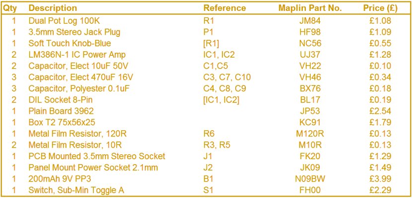
I suggest you find a 3.5mm plug ready moulded on a lead rather than buy one of Maplins plugs because the cable restraint is rather poor. Cheap heaphones or a PC audio lead will do and you'll probably find one cheaper.
As for the Mains charger, if you haven't got one lying about or can't find one at a boot sale I don't think this project is for you! Just make sure it a 12V DC output (I found an AC one first time round). If the plug is a slightly different size then make sure the socket you buy matches. (You can get 5.5mm jacks with 2.1mm and 2.5mm bores so be very careful. One way won't fit and the other will give intermittent contact). The other thing to watch is the polarity. Most chargers are pin positive but not all. If your's isn't you have to swap the schematic to match.
Modified Circuit Schematic
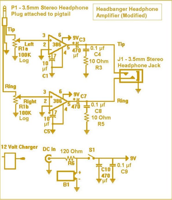
I've left the component references unchanged for easy comparison. If you look closely you'll see R6 has changed from 330 ohm to 120 ohm. It probably depends on the charger you're using but mine was only 12V without load and I found the charging current to be a bit too low. Maybe the use of a NiMH battery makes a difference too? I set the resistor to give about 30mA with the amp switched off.
NiCads are now difficult to get and more expensive, so you better off getting a NiMH and worrying about the crude charging circuit...
Board Layout
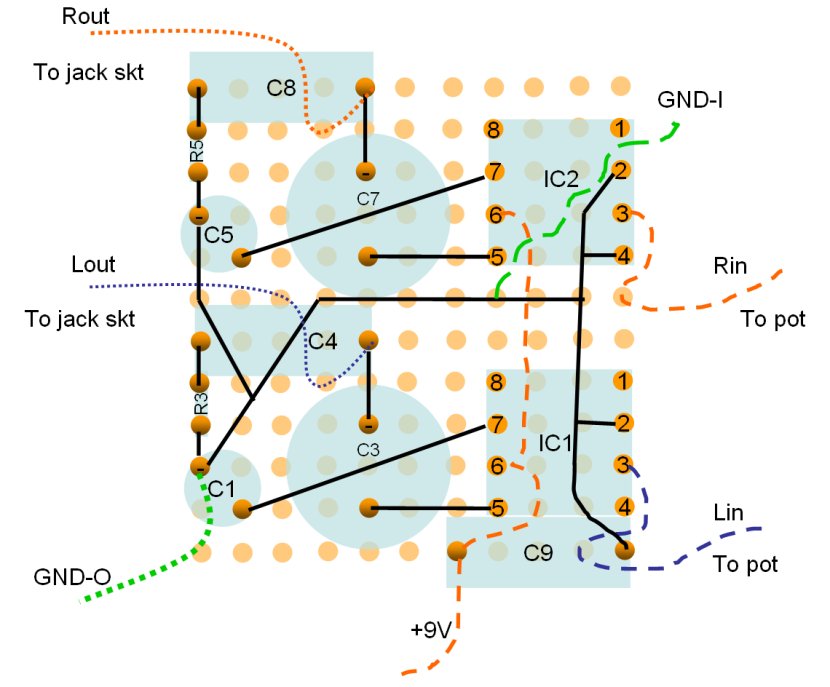
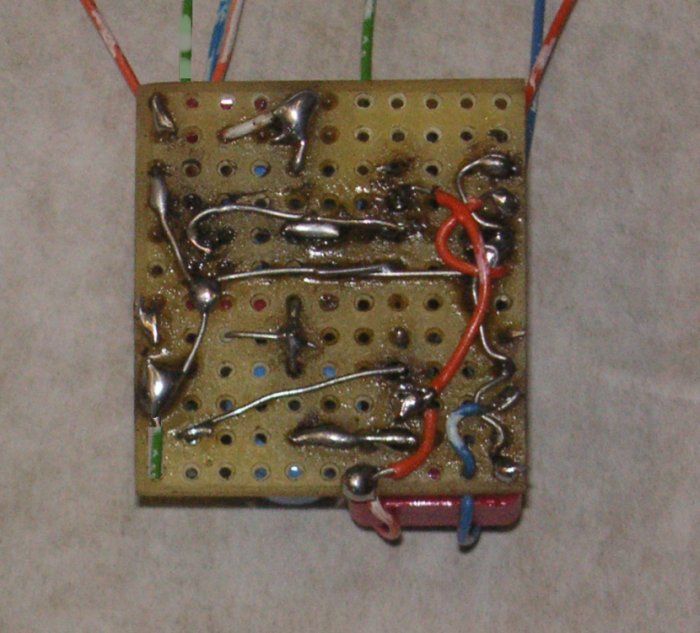
This is a view of the bottom of the board (solder side). After you've put in a few components read this again, SOLDER SIDE!
It should look a bit like this from the bottom...
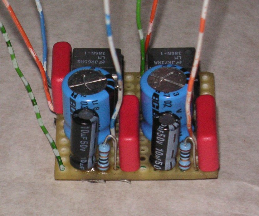
and this from the top...
Most of the links are made from component wire but where they need insulating I used telephone cable as it only has a single core. All the connection wires were stripped from telephone wire too, you may have recognised the colours!
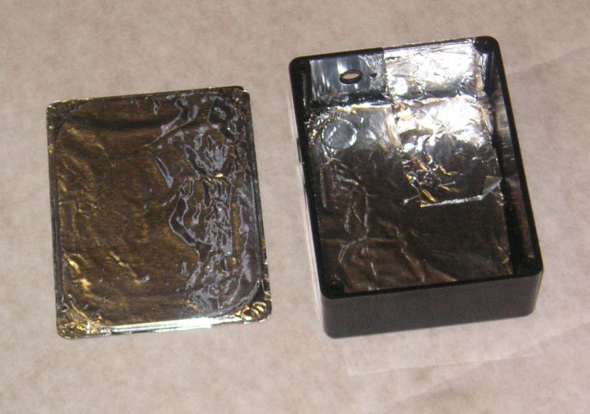
Box Preparation
I thought you'd prefer to get on with the board but you've really got to start the case now. If you've used the Maplin T2 box then it can be drilled like this:
Assembly
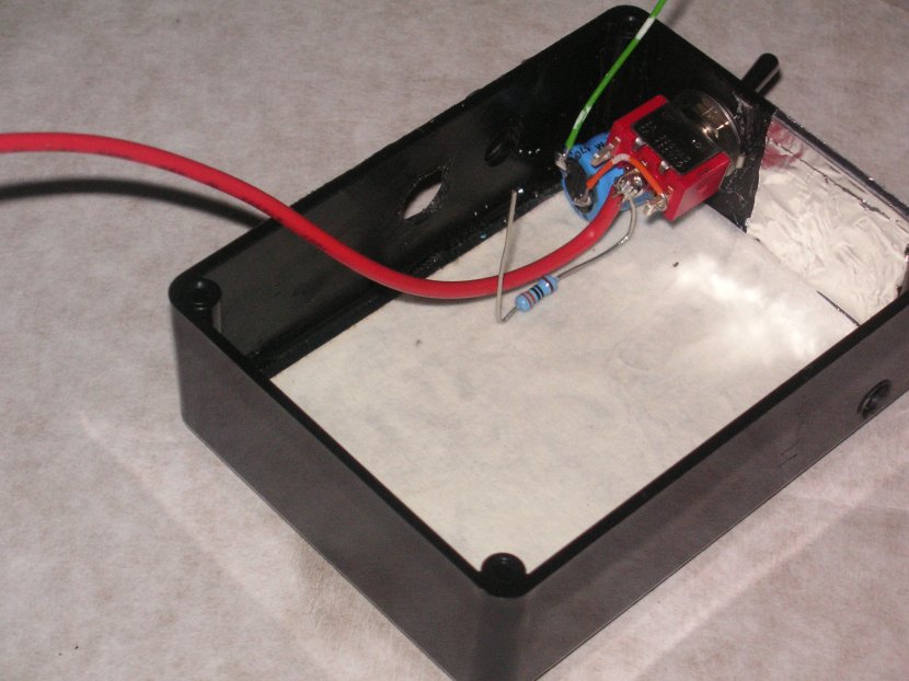
I'm not sure whether screening the box is important but I lined it with aluminium cooking foil along the bottom and under the pot. I allowed it to sit over the edge of the cover a little bit and also lined the cover. To prevent a short I covered the foil with masking tape where it mattered.
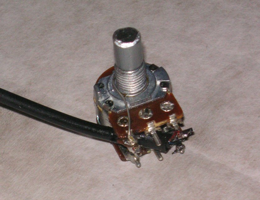
The pot requires an earth wire under the nut and the shaft cutting back to 10mm length.
When fitting the switch, I arranged for it to move in the horizontal plain with off being with the toggle nearest the pot. This ensures if it gets knocked in your pocket, it always switches off. Capacitor C10 is trapped underneath it. The charging resistor R6 is also fitted into the box.
After this it's just a case of assembling the bits into the box.
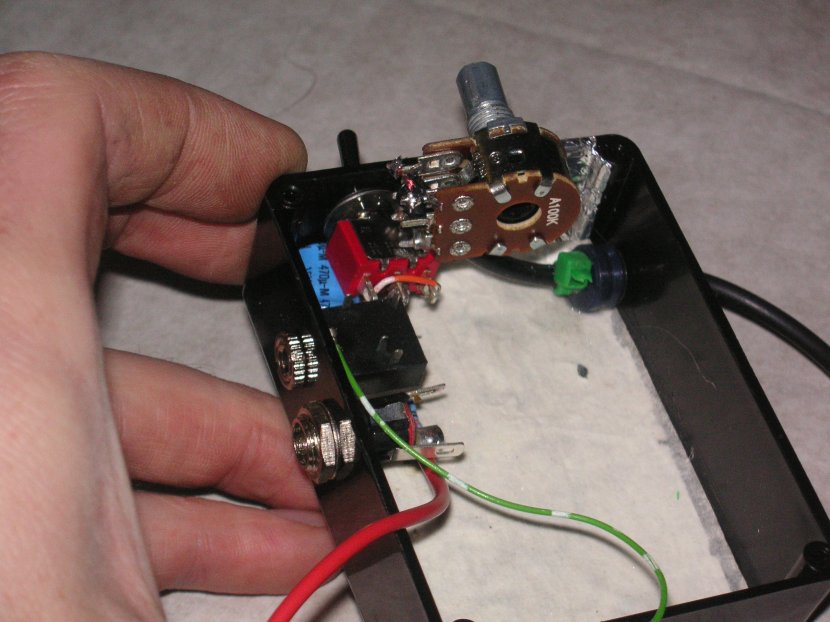
Fitting the knob on the pot is the most difficult job of the project, seriously, you'll find it extremely tight. Make sure you turn the volume right down to the bottom and definetly support the back of the shaft. I damaged the track on the first one I built and it looses one channel down low.
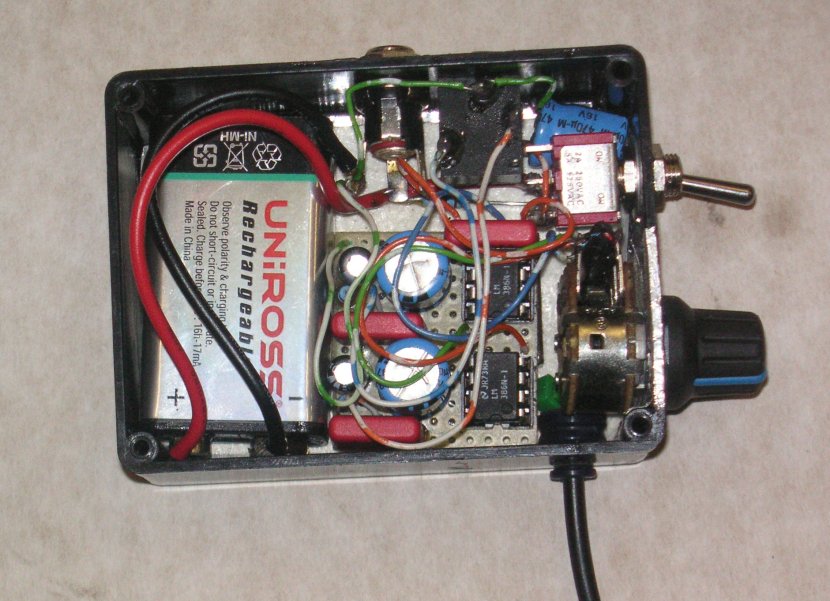
When the box is finished solder up the connection wires, leave them long to aid soldering, they will easily fold on top of the components when the board is mounted. Stick the main board onto a piece of double sided foam to keep it in place. (You may want to position the battery temporarily as it's a tight fit. I didn't use a battery connector as the Maplin one is hard plastic and wouldn't fit in the box. I think a flexible one will but as the battery isn't likely to come out I soldered it directly.
The finished unit should look like this...
The flying lead has the 3.5mm jack plug on for connection to the headphone socket of the player.
Screw on the lid, sit down in a darkened room, turn up the volume and enjoy!
home • inspiration • motorcycles • brakes • caravans • robotwars • flying • cars • projects • links • sitemap
E-mail: web@thewombles.net
© Splash_Womble